The Engineering of Precision: A Deep-Dive into Sheetfed Offset Press Construction & Tolerances
A sheetfed offset press operating at 18,000 sheets per hour tolerates mechanical misalignment of no more than ±0.01 mm across its cylinder train. That figure alone defines the engineering challenge — and the commercial stakes.
Sheetfed offset printing presses are not assembled; they are engineered to tolerance.
Every sub-system — from the press frame to the delivery gripper bars — operates within parameters that determine whether a 100,000-sheet run meets contract colour specifications or ends up in the waste bin.
For plant managers, procurement directors, and press technicians, understanding press construction is not academic.
It is the foundation for informed capital investment, effective preventive maintenance, and root-cause fault diagnosis.
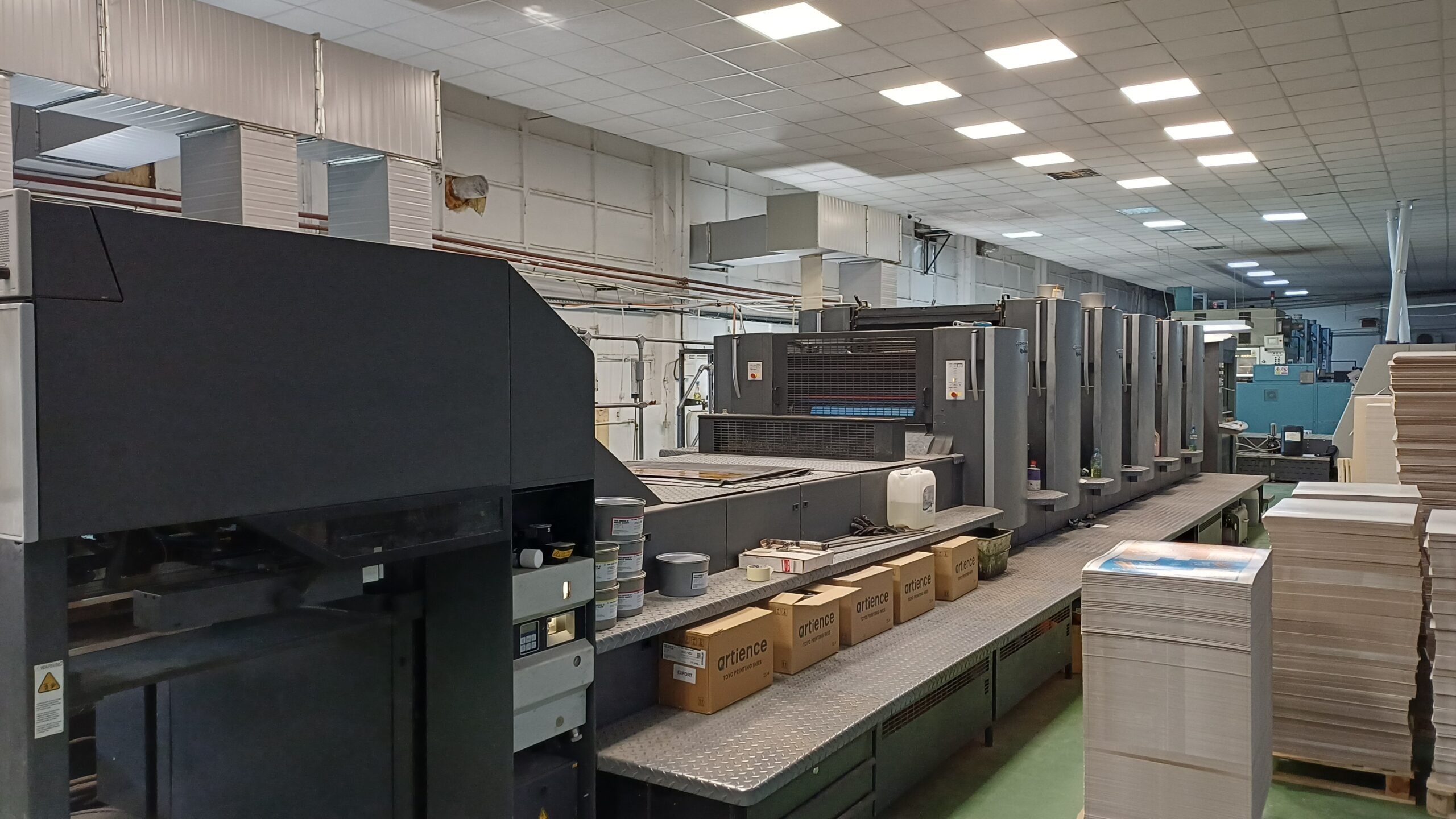
This article examines every major sub-system of a sheetfed offset press in the sequence in which they interact during production — from substrate input to delivered pile.
The Press Frame: The Tolerance Keeper
Material Specification and Load Dynamics
The press frame is manufactured from high-grade grey cast iron or welded structural steel plate, typically stress-relieved through controlled thermal cycling after fabrication.
Grey cast iron remains the preferred material for high-speed presses due to its superior vibration-damping coefficient — critical when a 5-colour press is running at 15,000+ sph and each impression cylinder strike generates an impulse load through the entire structure.
Side frames — the two main structural walls between which all cylinders are mounted — are precision-bored to concentricity tolerances measured in microns.
Bore misalignment between left and right side frames, even at 0.02 mm, produces taper across the impression nip, translating directly into uneven ink lay and dot gain variation across the sheet width.
Foundation and Installation
Press installation on a factory floor is not a placement exercise.
It is a precision leveling operation.
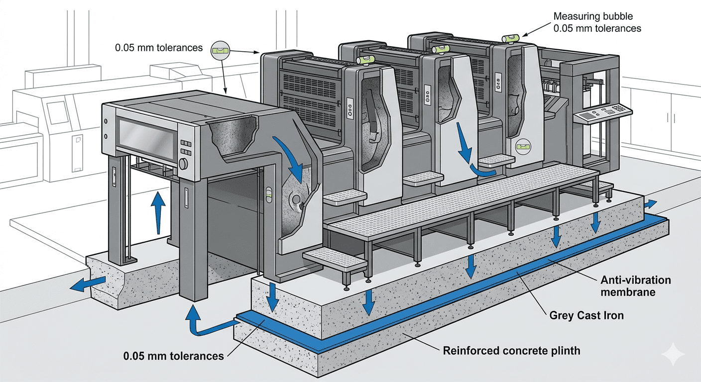
A standard 4-colour A1-format sheetfed press weighs between 18 and 35 tonnes depending on configuration.
To ensure mechanical stability, precise sheet transport, and accurate colour registration, a sheetfed offset printing press must be leveled to a tolerance of approximately 0.05 mm per meter over the entire machine length.
Achieving this level of installation accuracy typically requires precision anti-vibration leveling mounts.
In high-end commercial printing plants, presses are often installed on reinforced, isolated concrete plinths designed to absorb dynamic loads and prevent vibration transmission to adjacent equipment and the building structure.
Inadequate floor loading or poor leveling is one of the most under-reported causes of register drift on presses that were performing correctly at time of installation.
The Cylinder Train: Engineering the Impression
The three-cylinder offset printing unit — plate, blanket, and impression — constitutes the mechanical heart of the press.
Each unit in a multi-colour press replicates this configuration, and each must be synchronised to within microseconds of every other unit to achieve acceptable front-to-back register.
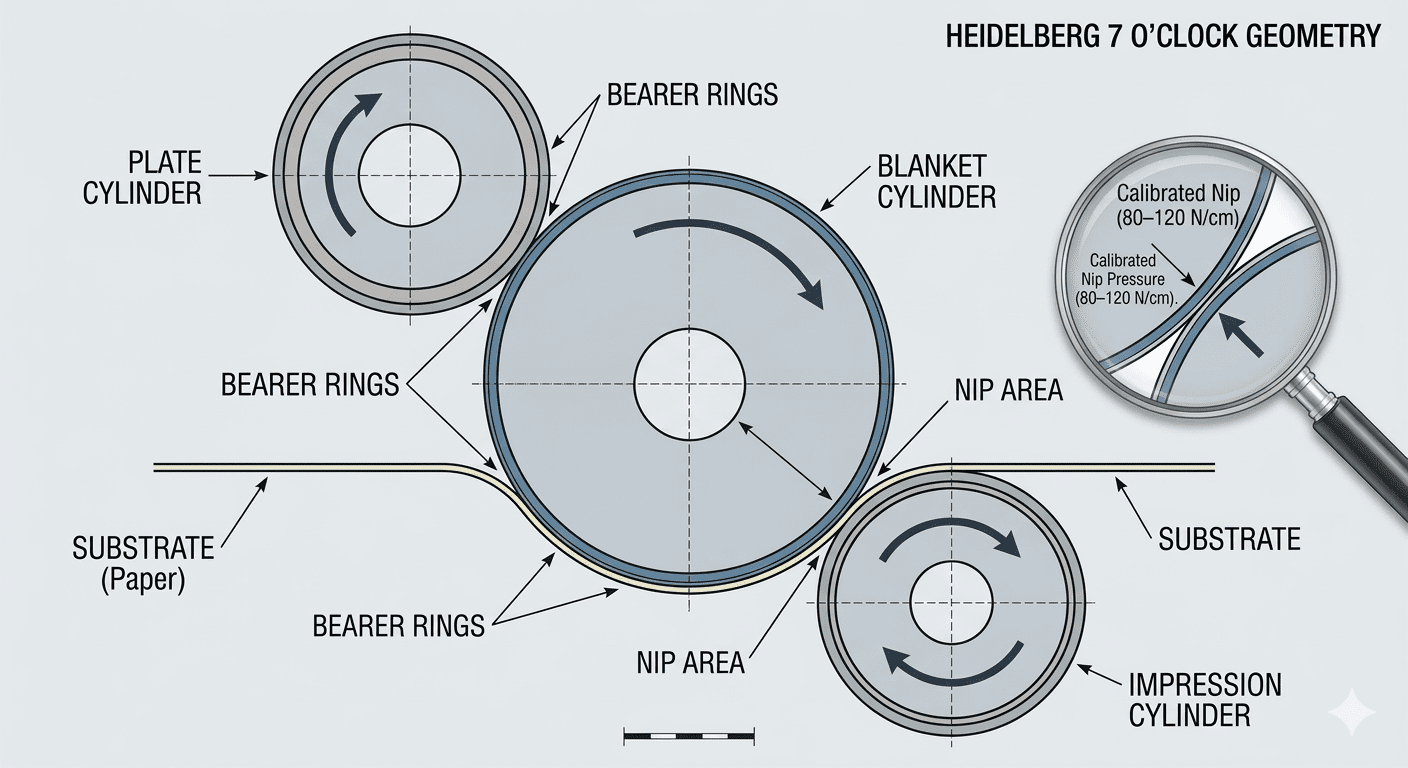
Plate Cylinder: Holding the Image with Precision
The plate cylinder carries the lithographic printing plate — typically a 0.15–0.30 mm anodised aluminium substrate exposed via a Computer-to-Plate (CtP) imaging system.
The cylinder diameter is engineered so that one full rotation equals exactly one sheet length at the specified print format.
Plate lock-up mechanisms — conventional bar clamps or quick-release automatic systems on modern presses — must hold plate position to within ±0.005 mm to maintain consistent front-to-back registration throughout the run.
Bearer rings, ground to the same diameter as the pitch circle of the cylinder gears, make contact between adjacent cylinders and carry a portion of the impression load, reducing gear tooth deflection under pressure.
Bearer contact pressure — typically 80–120 N per centimetre of bearer width — is a critical setting that operators must monitor, as it affects both print quality and gear wear rates.
Blanket Cylinder: The Offset Principle in Practice
The rubber blanket — a multi-ply construction of fabric carcass, compressible intermediate layer, and precision-ground surface layer — is the defining component of offset printing.
Its compressibility (typically 0.10–0.15 mm at operating pressure) allows it to conform to substrate surface irregularities, enabling quality printing on uncoated and textured stocks that would destroy a direct lithographic plate within minutes.
Blanket cylinder undercut — the difference between bearer height and the cylinder body diameter — is engineered to match blanket packing thickness precisely.
Incorrect packing height, even by 0.05 mm, alters impression pressure and print density.
This is not a theoretical concern: incorrect blanket packing is one of the three most common causes of tonal inconsistency identified during press audits.
Impression Cylinder: Managing Nip Pressure
The impression cylinder delivers the substrate through the blanket-impression nip under controlled pressure.
On a correctly set-up press, nip pressure is calibrated to transfer approximately 95–98% of available ink film from blanket to substrate surface.
Excessive impression pressure — a common response to poor ink transfer — does not compensate for ink or chemistry problems; it accelerates blanket wear and creates mechanical stress that propagates through the cylinder bearings.
Critical Tolerance Reference — Cylinder Sub-System:
| Component | Critical Tolerance | Operational Impact |
| Plate Lock-up | ±0.005 mm | Front-to-back register consistency |
| Bearer Rings | <0.002 mm TIR | Impression stability; reduced gear wear |
| Blanket Undercut | ±0.025 mm | Controlled dot gain; ink transfer density |
| Impression Nip | 80–150 N/cm | Transfer efficiency; extended blanket life |
| Cylinder Gears | <5 µm pitch error | Eliminates repeat defects (gear streaks) |
The Inking System: Controlled Rheology at Production Speed

A conventional offset inking system contains between 16 and 22 rollers, each performing a specific rheological function.
The combined surface area of these rollers — in contact with an ink film measured in microns — must deliver ink to the pla with zoneste at a consistency that allows less than 2% tonal variation across the sheet width and throughout the run length.
Ink Train Architecture
The ink fountain (duct) contains the ink supply, metered by a duct blade whose clearance from the fountain roller is adjustable in zones — typically 32 or 64 zones across a full-format press — via remotely controlled servo motors.
These zone adjustments are the primary tool for balancing ink density across the sheet and are now managed by closed-loop spectrophotometric control systems on modern presses.
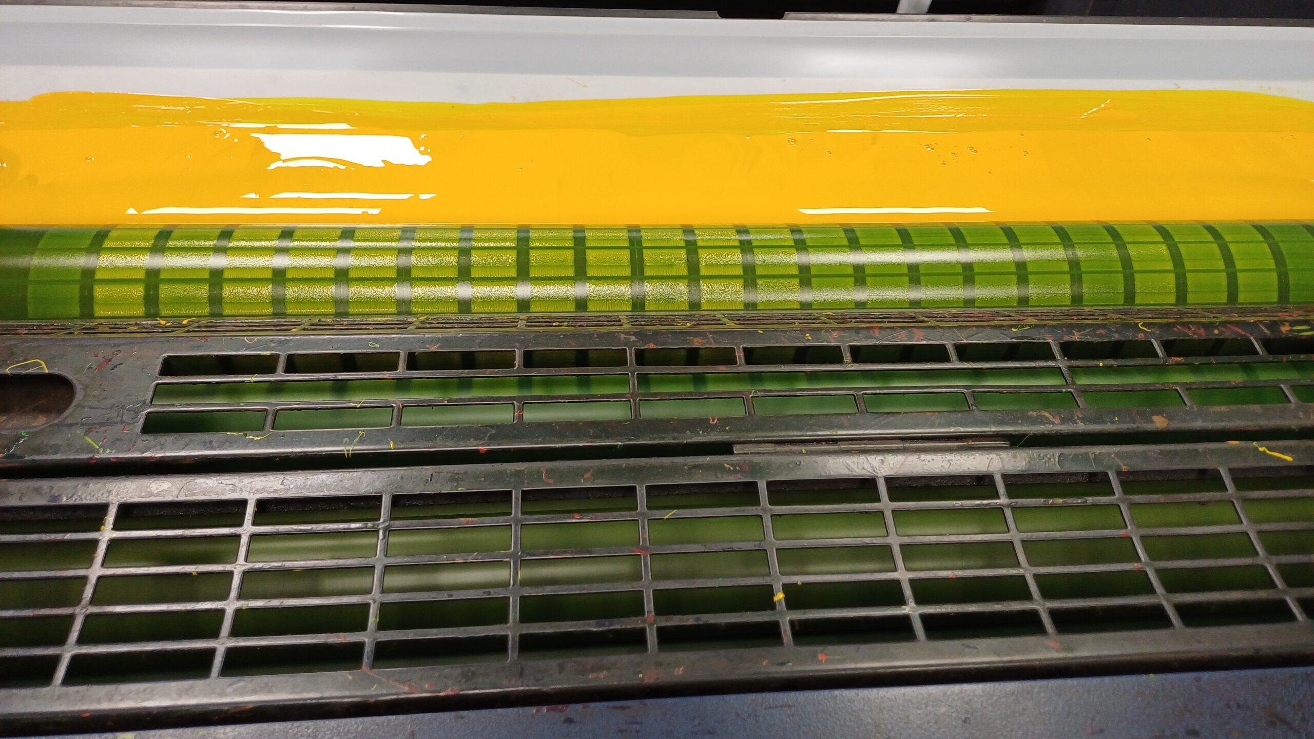
Distribution rollers — oscillating (reciprocating) rollers that traverse axially while rotating — are the system’s homogenising element.
Their axial stroke frequency and amplitude must be matched to press speed to prevent ghosting: the partial ink starvation pattern that appears when the inking system cannot recover between successive impressions.
Form rollers (typically 3 or 4 per inking unit) apply the conditioned ink film directly to the plate surface.
Their contact pressure with the plate must be set to achieve a ‘stripe’ width of 5–7 mm — tight enough for controlled transfer, not so heavy as to cause plate wear or ink slurring.
Electronic Ink Zone Control
Contemporary presses — Heidelberg Speedmaster, KOMORI Lithrone, Man Roland sheetfed, KBA Rapida — integrate CPC (Central Print Control) or equivalent systems that link zone settings to CIP3/CIP4 pre-press data.
Ink key presetting from digital job data reduces make-ready waste by 40–60% compared to manual set-up, a figure with direct impact on cost-per-thousand calculations for short-run digital offset work.
The Dampening System: Chemistry Meets Mechanics
Offset lithography depends on the selective wettability of the plate surface — image areas accept ink and repel water; non-image areas accept water and repel ink.
The dampening system maintains this chemical boundary at every impression.
Integrated vs. Conventional Dampening
Conventional dampening systems (e.g., brush dampeners) have been largely superseded in commercial press manufacturing by integrated dampening systems — Alcolor (Heidelberg), Dahlgren, or equivalent continuous-feed designs — that feed fountain solution through a chain of film rollers directly into the ink train.
This integration reduces water consumption, minimises water-ink emulsification imbalance, and shortens start-up waste.
It isn’t enough for a dampening system to just keep the plate wet; it has to keep it clean.
High-performance units solve this through a differential drive, commonly known as the Delta-effect.
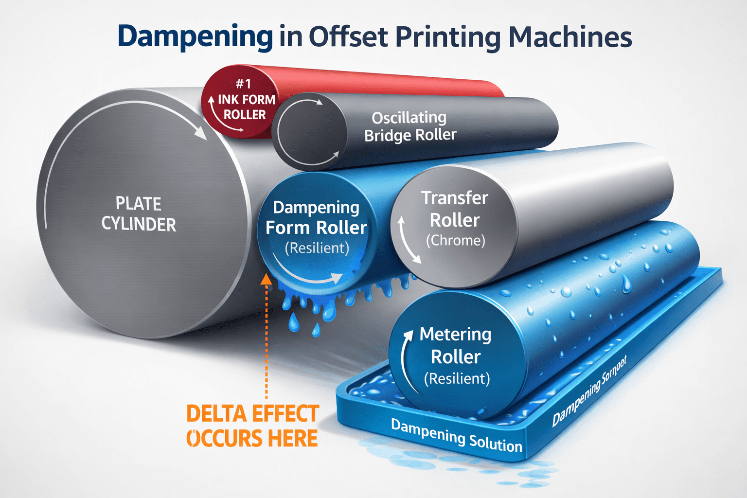
By running the dampening form roller at a surface speed roughly 10%–15% different from the plate cylinder, the press creates a constant, microscopic “wiping” action.
This mechanical shear effectively scrubs away dust and ink skin (hickeys) before they can reach the blanket.
It’s a subtle engineering choice that pays dividends in the pressroom—reducing manual stops for plate washing and keeping the “zero-touch” workflow moving during long-run production.
Fountain solution (dampening water) composition is critical: pH maintained at 4.8–5.5, conductivity at 800–1,500 µS/cm, isopropyl alcohol (IPA) concentration at 8–12% or alcohol-substitute equivalent.
These are not preferences — they are process parameters.
Deviation produces scumming (ink in non-image areas), water marks, or ink emulsification, all of which require press stops and waste investigation time.
Temperature Control
Modern dampening systems include chilled water circuits maintaining fountain solution temperature at 10–15°C.
Temperature stability prevents viscosity drift in both the dampening solution and the ink, a factor that becomes commercially significant on runs exceeding 50,000 sheets where temperature-induced density creep would otherwise require multiple ink adjustments.
Sheet Handling: The Mechanical Logistics of Substrate Control
A sheetfed press running at 18,000 sph is feeding, positioning, printing, and delivering five sheets per second.
The sheet handling system must execute this without damage, misregister, or double feeding — at any substrate weight from 60 gsm lightweight stocks to 600 gsm folding boxboard.
Feeder: Air and Suckers
The feeder pile is de-riffled and fanned by an air blast system before the first sheet is lifted. Suction cups — typically 8 to 12 in a row — lift the top sheet, verified by ultrasonic or mechanical double-sheet detectors before it is released to the feed rollers.
Detection sensitivity must be calibrated per job: a double-sheet of 80 gsm coated is 0.20 mm thick; at 300 gsm, the geometry changes entirely.
Sheet forwarding from the feeder to the front lays takes place via a series of feed rollers and suction tape transport systems.
Timing is critical: each sheet must arrive at the front and side lay stops within ±0.1 mm of its specified position, every cycle, across the full run.
Register and Gripper Systems
Front lays (typically 3) and a single side lay establish the sheet’s reference position before it is taken by the first transfer gripper.
Gripper bars — spring-loaded clamps spaced across the full sheet width — must apply uniform clamping force (typically 15–25 N per gripper finger) to prevent sheet slip during impression.
Gripper timing is controlled by cam mechanisms; any wear in the cam profile produces inconsistent gripper opening that manifests as front-lay register variation.
Delivery: From Press to Pile
The delivery section decelerates the printed sheet from press speed to zero, deposits it onto the delivery pile, and jogs it into register using side and rear tampers.
Sheet braking is typically achieved by a combination of sheet slowdown brakes and air blast systems.
On high-speed presses, anti-set-off powder spray systems deposit fine starch particles between sheets to prevent wet ink transfer between the printed face and the reverse of the sheet above.
Automation, Closed-Loop Control, and Press Intelligence
The mechanical sub-systems described above are necessary conditions for quality print.
They are not sufficient.
At modern production speeds, manual operator response time is too slow to prevent scrap accumulation when process variables drift.
This is where press control architecture separates entry-level machines from capital-grade equipment.
Inline Measurement and Closed-Loop Feedback

Spectrophotometric measurement systems — mounted in the delivery section or at a dedicated inline measurement station — scan printed colour bars on every nth sheet (configurable, typically every 30–200 sheets depending on run sensitivity).
Measured L*a*b* values are compared against proof or contract standard.
Deviations exceeding set tolerances (typically ΔE < 2.0 for commercial work, < 1.0 for brand-critical packaging) trigger automatic ink zone corrections without operator intervention.
Systems such as Heidelberg Prinect Inpress Control, KOMORI PDC-SX, and KBA QualiTronic PhotoElectric operate on this principle.
The return on investment is not theoretical — closed-loop colour control typically reduces colour-related waste by 15–25% on high-volume runs and virtually eliminates the need for operator colour pulls.
Job Change Automation
Automatic plate changing (APC) systems mount, unmount, and register new plates in under two minutes per printing unit without operator involvement beyond initiating the sequence.
On a 5-colour press, a full plate change cycle — previously requiring 20–30 minutes of skilled operator time — completes in under 5 minutes.
For operations running more than 8 job changes per shift, this single capability changes the economics of short-run commercial printing.
Predictive Maintenance Integration
Leading press OEMs now offer IoT-connected press monitoring — Heidelberg Assistant, ManRoland PRINTNET, KOMORI KP-Connect — that track motor load, bearing temperature, gripper force, and lubrication intervals in real time.
Anomaly detection algorithms flag developing faults before they cause press stops.
Operators should not mistake these systems for maintenance replacements; they are decision-support tools that require trained engineers to act on the data they surface.
Capital Investment Perspective: What Construction Quality Means for TCO
Press construction quality is not visible on a showroom floor.
It lives in bearing clearances, in the grade of cast iron used for the frame, in the quality of the gear grinding.
These factors surface in total cost of ownership (TCO) over a 15–20 year press life — the realistic operational horizon for well-maintained capital equipment.
A press bought on acquisition price alone, without evaluating cylinder bearing design, side-frame material specification, and OEM service infrastructure, will recover its apparent saving in avoidable downtime within the first three years.
Key construction-quality indicators to evaluate in any press procurement process:
side-frame material and stress-relief certification;
cylinder bearer ring specifications;
ink train roller count and oscillation range;
dampening system type (integrated preferred);
feeder double-sheet detector type;
and the availability and cost of CPC/inline measurement options as retrofits or factory-fit.
The difference between a press built to ±0.005 mm cylinder concentricity and one built to ±0.02 mm is not apparent in the brochure.
It becomes apparent at 8,000 hours of operation under production conditions.
The Future Outlook: IoT and the “Zero-Touch” Maintenance Era
The precision engineering of the sheetfed offset press is entering a new phase where mechanical tolerances are no longer just monitored by technicians with feeler gauges, but by a continuous stream of sensor data.
As we move toward a “Zero-Touch” production environment, the physical sub-systems described in this article are being outfitted with Industrial IoT (IIoT) capabilities.

Real-Time Vibration & Acoustic Analysis
High-grade grey cast iron frames are now being paired with high-frequency accelerometers.
These sensors detect “micro-chatter” in the cylinder train—vibrations invisible to the human eye—that signal a bearing is beginning to fatigue or a gear pitch is drifting.
By analyzing the frequency of the vibration, AI-driven platforms can predict a mechanical failure weeks before it causes a 5 µm streak on a high-end packaging job.
Digital Twin Synchronization
Modern press control systems are creating “Digital Twins” of the mechanical train.
The system compares the real-time energy draw of the motor and the heat signature of the ink rollers against a “perfect” digital model.
If the friction in the dampening system rises by even 2%, the press flags a maintenance alert, ensuring that the ±0.01 mm tolerance is maintained through data-backed intervention rather than reactive repair.
Agentic AI in the Pressroom
The goal of the “Zero-Touch Revolution” is to move the press technician from a manual troubleshooter to a data orchestrator.
When the inline spectrophotometer detects a ΔE deviation, Agentic AI doesn’t just adjust an ink key; it correlates that data with the current temperature of the chilled fountain solution and the age of the blankets to suggest a root-cause fix.
Engineering as Competitive Advantage
A sheetfed offset printing press is not a purchase.
It is a 15-year capital commitment that will shape the cost structure, substrate capability, and quality ceiling of every job that runs through it.
The construction quality of its frame, the precision of its cylinder train, the architecture of its inking and dampening systems, and the intelligence of its control platform collectively determine whether that machine is a profit engine or a liability.
Understanding press construction at the sub-system level allows print operations management to ask better questions during procurement, write tighter maintenance specifications, diagnose quality defects faster, and make defensible capital replacement decisions.
That understanding begins with the mechanics — and extends to the data the press generates at every impression.
Operators run jobs.
Engineers maintain presses.
Executives set the parameters within which both operate.
The best-performing print operations are those where all three levels of knowledge are connected — through training, through data, and through a shared understanding of what precision engineering actually requires.