
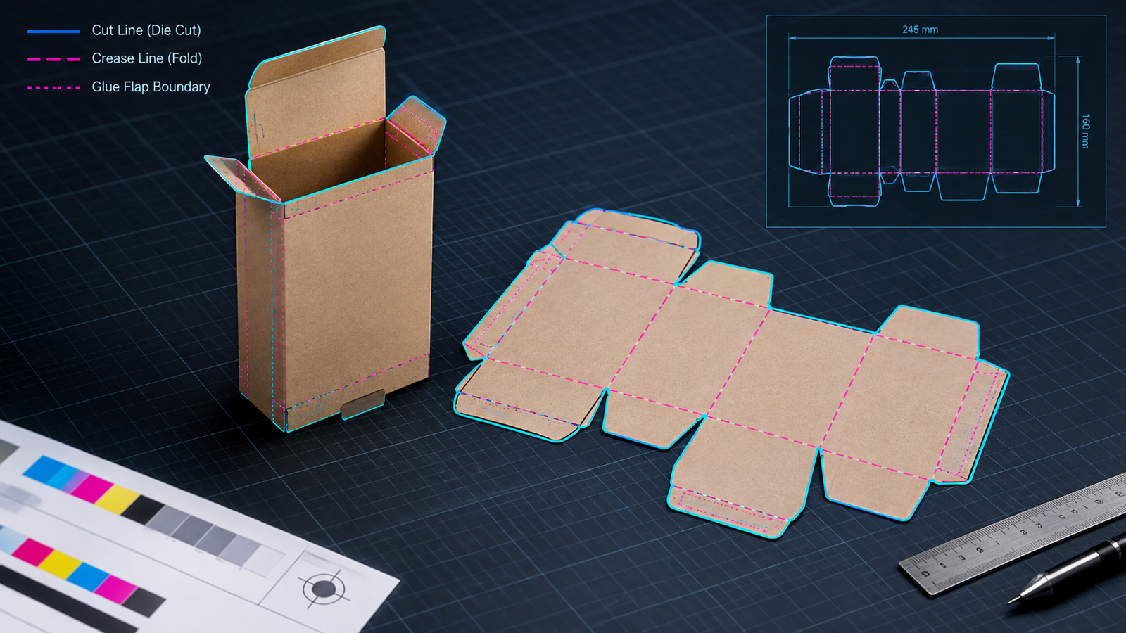
A key line drawing in packaging (KLD in Packaging) is a flat, 1:1 scale technical drawing of a packaging structure showing cut lines, crease lines, perforations, and glue flaps.
Most converters treat KLD and dieline as synonyms.
Die-makers build the cutting die from the KLD geometry, and prepress places artwork, typical 3 mm bleed, and safe zones on the drawing.
What Does a KLD in Packaging Contain?
A KLD in packaging contains cut lines, crease lines, perforation lines, glue flap areas, bleed boundaries, and safe zone boundaries, all drawn at 1:1 scale in vector format.
Each line type carries a distinct stroke style or named separation so that the die-maker reads tooling instructions directly from the drawing.
| Parameter | Value or Range | Unit | Test Method or Instrument | Note |
| Cut line (solid stroke) | 0.09–0.35 (0.25–1) | mm (pt) | Separation preview in preflight software (automated print-file checker) | Drawn as a spot color, a named ink separation outside the process inks |
| Crease line (dashed stroke) | 0.09–0.35 (0.25–1) | mm (pt) | Separation preview in preflight software | Becomes the creasing rule in the die |
| Perforation line (dash-dot stroke) | 0.09–0.35 (0.25–1) | mm (pt) | Separation preview in preflight software | Becomes the perforating rule in the die |
| Glue flap area (typical width) | 12–20 (0.5–0.8) | mm (in) | Steel rule on plotted sample | Varnish-free zone for adhesive bonding |
| Dimension callouts | Varies by product | mm (in) | Digital caliper on the product | Internal dimensions set product fit |
KLD vs Dieline: Are the Terms Interchangeable?
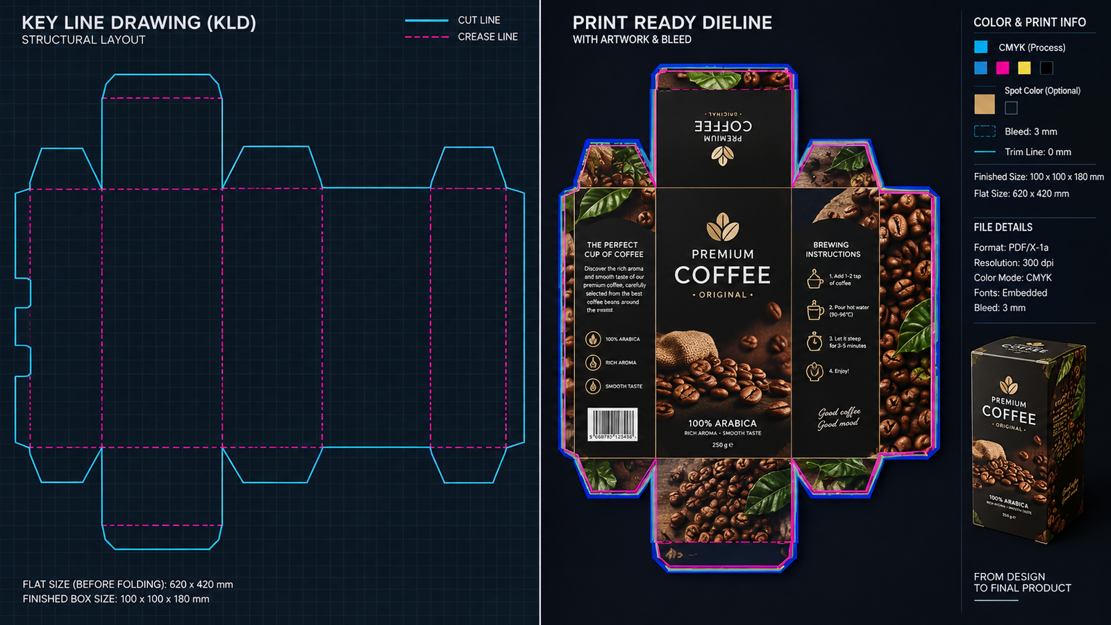
KLD and dieline name the same flat 1:1 structural drawing in most converter workflows.
KLD is the term in South Asian packaging trade, while dieline dominates North American and European usage.
Some shops reserve KLD for the converter-supplied line-only drawing and dieline for the layered file that already carries artwork.
| Attribute | KLD | Dieline | Selection Criterion |
| Regional usage | South Asian converters and agencies | North American and European converters | Use the term printed on the purchase order |
| Typical scope | Line-only structural drawing | Structural lines plus artwork layers | Request the line-only file before designing artwork |
| Resulting tool | Cutting and creasing die | Cutting and creasing die | Treat the terms as equal for tooling |
How Does a KLD in Packaging Move From Design to Die-Cutting?
A KLD moves from structural design to die-cutting in seven stages: dimension capture, structural computer-aided design (CAD) drawing, sample plotting, artwork placement, preflight, die-making, and press-to-die registration check.
Each stage preserves 1:1 scale so that printed artwork aligns with cut and crease positions on the finished carton.
- Measure the product with a digital caliper and record internal length, width, and height in millimeters.
- Draw the structure in CAD at 1:1 scale and apply crease offsets for the board caliper measured in micrometers (µm).
- Plot a white sample on a digital cutting table and confirm that the folded carton closes square without forced fit.
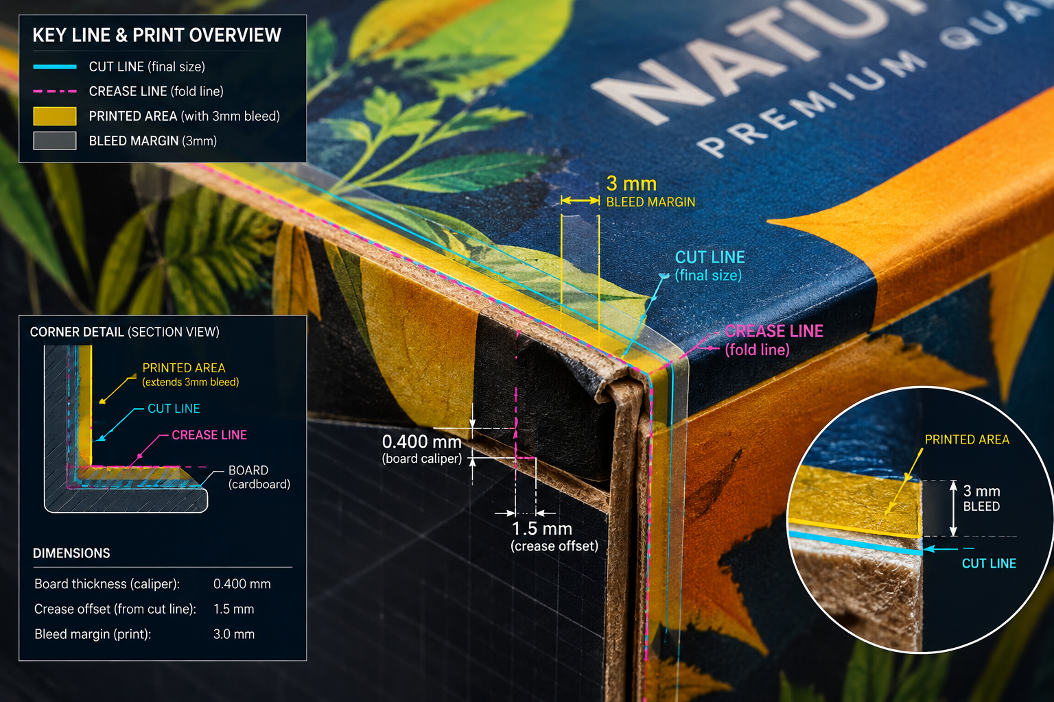
- Place artwork on a separate layer with 3 mm bleed beyond each cut line and a 3 mm safe zone inside the cut lines.
- Run preflight and confirm that KLD lines are overprint strokes, which print over underlying ink without knockout, and sit on a non-printing layer.
- Release the approved KLD to the die-maker with the version number printed on the file and recorded on the die.
- Measure print-to-cut registration on the first die-cut sample against the converter tolerance, typically ±0.5 mm to ±1 mm, using a loupe.
Which Parameters Control KLD Accuracy in Prepress?
KLD accuracy depends on seven controlled parameters: scale, spot color definition, overprint setting, bleed, safe zone, board caliper compensation, and print-to-cut registration tolerance.
Typical values are 1:1 scale, 3 mm bleed, 3 mm safe zone, and ±0.5 mm to ±1 mm registration, but converters publish their own limits.
| Parameter | Value or Range | Unit | Test Method or Instrument | Note |
| Scale | 1:1 | ratio | Measurement tool in a Portable Document Format (PDF) viewer | Scaling shifts cut and crease positions |
| Spot color definition | Not specified by standard | Not applicable | Separations panel in preflight software | One named spot color per line type lets the die-maker filter lines |
| Overprint setting | Enabled | Not applicable | Overprint preview in preflight software | Prevents knockout of underlying artwork |
| Bleed (typical) | 3 (0.125) | mm (in) | Steel rule on plotted proof | Converter range is 2 mm to 5 mm |
| Safe zone (typical) | 3 (0.125) | mm (in) | Steel rule on plotted proof | Keeps text and logos clear of cutting variation |
| Board caliper compensation | 250–600 (10–24) | µm (mil) | Digital micrometer per International Organization for Standardization (ISO) 534 | Typical folding carton board range |
| Print-to-cut registration tolerance (typical) | ±0.5 to ±1 | mm | Loupe and steel rule on first die-cut sample | Converter specification overrides the typical range |
Which Packaging Formats Use a KLD?
Folding cartons, corrugated cases, rigid boxes, paper bags, and die-cut labels all use a KLD, while flexible pouches use a related layout drawing with seal areas and repeat length.
Die-cut formats rely on steel-rule flatbed or rotary dies, and the KLD geometry defines the tool profile.
| Attribute | Folding Carton | Corrugated Case | Die-Cut Label | Selection Criterion |
| Line types present | Cut, crease, glue flap, perforation | Cut, crease, slot, hand hole | Kiss cut, perforation, waste matrix | Match line types to the required die rules |
| Substrate thickness, µm (mil) | 250–600 (10–24) | 1,200–4,000 (47–157) | Varies by laminate construction | Measure the actual material before drawing crease offsets |
| Typical die | Flatbed steel-rule die | Flatbed or rotary steel-rule die | Rotary die | Run length and press format decide flatbed versus rotary |
| Style code reference | Varies by converter library | European Federation of Corrugated Board Manufacturers (FEFCO) code 0201 for a regular slotted container | Not specified by standard | Request the style code from the converter |
What Causes KLD Errors in Prepress and Die-Cutting?
KLD errors originate from four sources: incorrect scale, missing bleed, non-overprinting cut lines, and outdated file versions.
Each error produces misaligned creases, white edges after trimming, or tooling lines on the plate.
Preflight at 1:1 scale catches the first three sources, and version numbering prevents the fourth.
| Symptom | Probable Root Cause | Diagnostic Check | Corrective Action | Acceptance Criterion |
| Folded carton does not close square | Crease offset ignores board caliper | Measure caliper with a micrometer and compare it with the KLD offset | Redraw creases with caliper compensation and re-plot the sample | Plotted sample closes square without forced fit |
| White edge after trimming | Background artwork stops at the cut line | Inspect the plotted proof at the cut line with a loupe | Extend background artwork 3 mm beyond the cut line | No white edge visible under a 10× loupe |
| Cut lines appear on the printed sheet | KLD layer remains on a printing separation | Review separations and overprint preview in preflight software | Delete the KLD layer from plate output or set it to non-printing | No KLD lines appear on any plate separation |
| Print shifts relative to cut | Die made from an outdated KLD version | Compare the version numbers on die and file, then measure the shift with a loupe | Release the current KLD version and remake the die if the versions differ | Shift stays within the converter tolerance |
| Glue flap fails adhesion | Varnish or coating covers the glue area | Compare the coating plate area with the glue flap boundary on the KLD | Knock out varnish and coating in the glue area | Fiber tear across the glue joint on pull test |
Standards and Technical References
- ISO 534, Paper and board: Determination of thickness, density and specific volume. International Organization for Standardization (ISO).
- ISO 15930 series, Graphic technology: Prepress digital data exchange using PDF (PDF/X). International Organization for Standardization (ISO).
- International Fibreboard Case Code (FEFCO code 0201 reference). European Federation of Corrugated Board Manufacturers (FEFCO) and European Solid Board Organisation (ESBO).
Frequently Asked Questions
Who Supplies the KLD: the Converter or the Brand Owner?
The converter supplies the KLD because the drawing must match the converter’s die-cutting equipment, board grade, and caliper. Brand owners and designers request the line-only KLD before artwork starts, since a redrawn structure introduces dimension errors that become visible only on the first die-cut sample.
What Stroke Weight Should KLD Lines Use?
KLD lines use stroke weights of 0.09 mm to 0.35 mm (0.25 pt to 1 pt), with the stroke centerline marking the exact cut or crease position. Strokes in this range remain visible in preflight views and avoid ambiguity about where the geometry sits relative to artwork edges.
Which File Format Should a Converter Supply for a KLD?
A vector PDF or Drawing Exchange Format (DXF) file preserves true 1:1 geometry and named line layers, while raster images lose dimensional accuracy. Press-ready artwork files commonly follow PDF/X, the print-exchange subset of PDF defined in ISO 15930, with the KLD kept on a separate non-printing layer.
Does Bleed Extend Past Crease Lines as Well as Cut Lines?
Bleed extends 3 mm past every cut line, including window cut-outs, but not past crease lines, because creases sit inside continuous substrate. Artwork crosses each crease without a break, and glue flaps receive 3 mm bleed at the outer cut edge to prevent white slivers after die-cutting.
Can a KLD Be Reused After a Board Caliper Change?
Any change in board grade or caliper requires KLD revision, because crease offsets and panel dimensions compensate for material thickness in micrometers. A converter verifies the revised drawing with a plotted white sample before die-making, and the new version number replaces the old file in every job folder.
How Do KLD Lines Differ From Trim Marks and Crop Marks?
KLD lines describe the packaging structure and die tooling, while trim marks and crop marks locate sheet edges for guillotine cutting. Marks sit outside the 3 mm bleed area and print on the sheet, whereas KLD lines stay on a non-printing separation and guide the die-maker only.