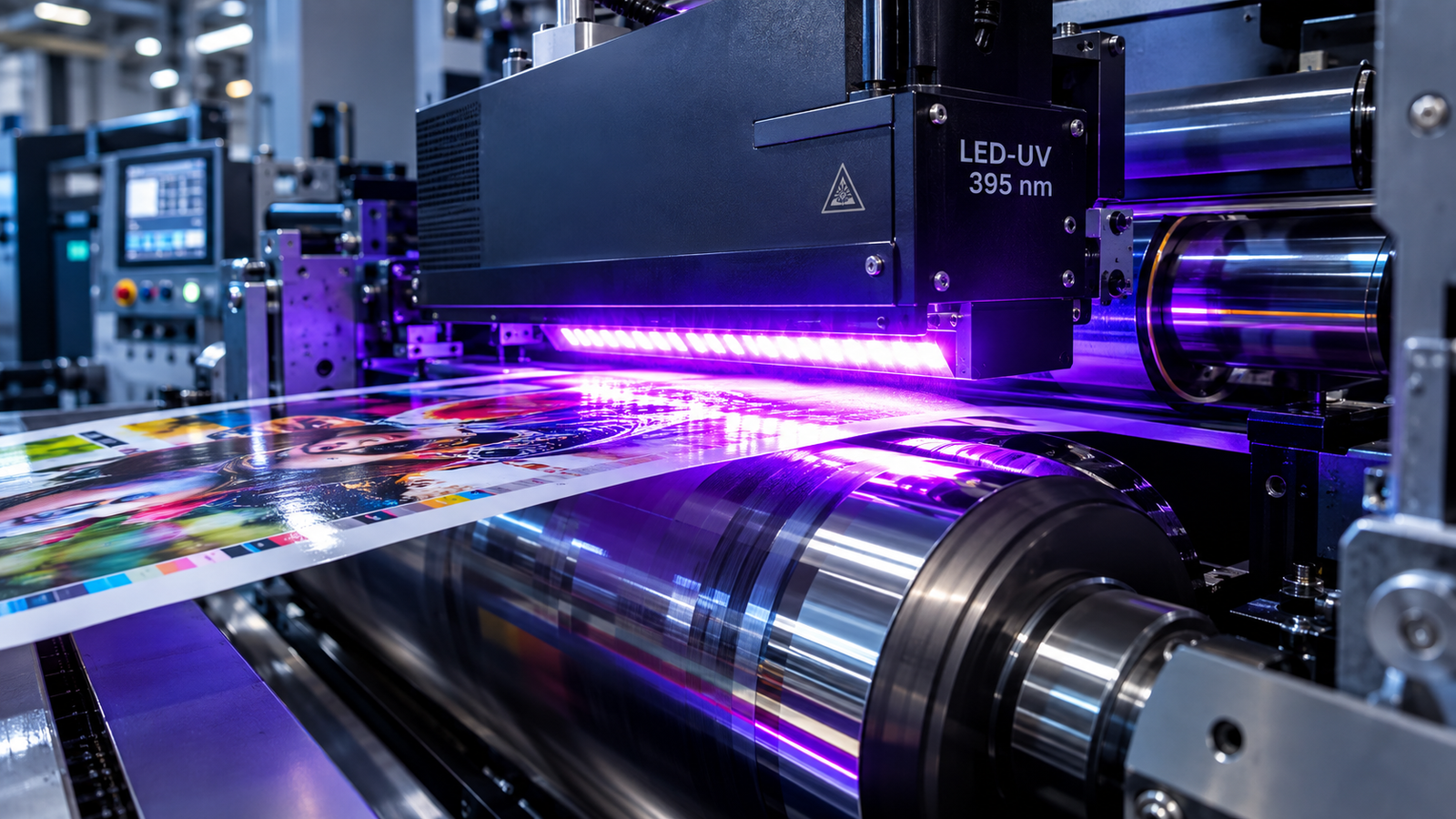
LED-UV curing emits a narrow 385, 395, or 405 nm band with no infrared or ozone, while mercury-arc curing emits broadband 200–450 nm radiation with emission peaks at 254, 313, and 365 nm.
LED-UV needs matched acylphosphine oxide photoinitiators; mercury-arc cures a broader ink range but adds heat and ozone.
What Are LED-UV and Mercury-Arc Curing Systems?
Ultraviolet light-emitting diode (LED-UV) and mercury-arc systems are lamps that polymerize offset inks and coatings by activating photoinitiators.
A mercury-arc lamp discharges through vaporized mercury to emit broadband ultraviolet light.
An LED-UV lamp uses diode arrays that emit one narrow wavelength band, and inks must carry photoinitiators tuned to that band.
Acylphosphine oxides such as bis-acylphosphine oxide (BAPO) serve as the photoinitiators matched to the LED-UV band.
For food-contact packaging, it is important to know that BAPO formulations must meet low-migration compliance guidelines (e.g., EuPIA / Swiss Ordinance).
Unlike mercury lamps, cool-operating LED-UV systems prevent substrate expansion and thermal ink degradation, effectively eliminating the primary root causes of color shifts in offset printing
How Does UV Curing Work in Offset Printing?
UV curing converts liquid offset ink into a solid film through photopolymerization.
Photons matching the photoinitiator absorption band cleave photoinitiator molecules into free radicals, and the radicals link acrylate monomers and oligomers into a polymer network as the sheet passes under the lamp.
Oxygen at the film surface consumes radicals and limits surface cure.
- Match lamp emission to the photoinitiator absorption band: 385, 395, or 405 nm (±5 nm) for LED-UV and 200–450 nm broadband for mercury-arc.
- Measure peak irradiance (W/cm²) at the sheet plane with a radiometer calibrated for the lamp peak wavelength. The reading must meet the ink supplier’s minimum.
- Calculate energy dose (cure dose, mJ/cm²) as irradiance (mW/cm²) multiplied by exposure time (s). Exposure time equals lamp window width divided by press speed.
- Verify surface cure at the delivery with a thumb-twist test. The film must show no tack, smear, or thumb transfer.
- Verify through-cure with tape, solvent, and crease tests. The film must not lift, dissolve, or crack per the ink supplier’s specification.
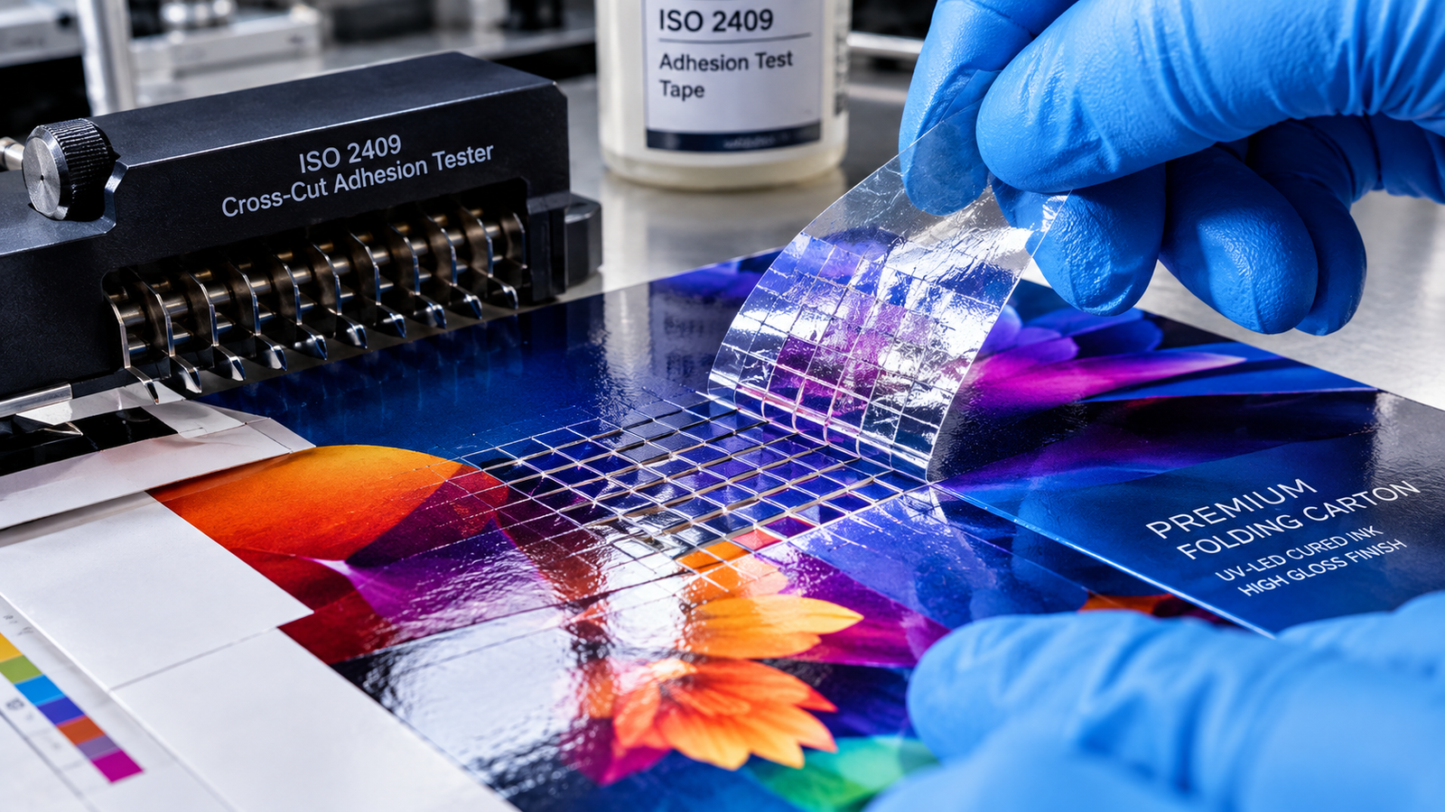
Verify adhesion with a cross-hatch tape test (ISO 2409 or ASTM D3359). No squares may lift.
Ensuring proper photoinitiator activation is essential when optimizing print quality with offset printing on non-porous synthetic substrates.
LED-UV vs Mercury-Arc Curing: Specification Comparison
LED-UV lamps last up to 20,000 hours against 1,000 to 2,000 hours for mercury-arc lamps, emit no infrared or ozone, and switch on instantly.
Mercury-arc lamps cure a broader ink range.
One B1 perfecting press example shows 612,000 kWh for LED-UV versus 1,210,000 kWh for H-UV over ten years, that is approximately 49 percent lower.
| Attribute | Mercury-Arc | LED-UV | Selection Criterion |
|---|---|---|---|
| Emission spectrum (nm) | Broadband 200–450; peaks at 254, 313, 365 | Narrow band at 385, 395, or 405 (±5) | Match spectrum to the ink photoinitiator absorption band |
| Infrared output and substrate heat | High infrared; heat and curl on thin films | No infrared emission; low substrate heat | Choose LED-UV for thin, heat-sensitive films |
| Ozone generation | Produces ozone; extraction required | None; no short-wave ultraviolet-C (UVC) | Plan extraction for mercury-arc installations |
| Switching | Warm-up and shutter operation | Instant on and off | Choose LED-UV for frequent stop-start runs |
| Lamp life (hours) | 1,000–2,000 | Up to 20,000 | Compare replacement interval with the maintenance schedule |
| Photoinitiator requirement | Broad ink compatibility | Acylphosphine oxides such as BAPO matched to the exact wavelength | Confirm the ink is formulated for the lamp band before conversion |
| Ten-year energy use, B1 perfecting press (kWh) | 1,210,000 (H-UV) | 612,000 (approx. 49% lower) | Treat as a single example; verify against site energy data |
Curing Parameters and Measurement Methods
Irradiance in W/cm² is radiant power per unit area at the sheet, and energy dose in mJ/cm² is irradiance multiplied by exposure time.
Both must be measured at the sheet plane with a radiometer calibrated for the lamp peak.
Surface energy, ink film thickness, and lamp distance complete the parameter set.
| Parameter | Value or Range | Unit | Test Method or Instrument | Note |
|---|---|---|---|---|
| Peak irradiance | 8 – 16 depending on the speed of the machine and the distance | W/cm² | Radiometer calibrated for the lamp peak, at the sheet plane | 1 W/cm² equals 1,000 mW/cm² |
| Energy dose | 15 – 35 depending on the layer thickness and pigmentation | mJ/cm² | Integrating radiometer | Irradiance multiplied by exposure time |
| Peak wavelength | LED-UV 385, 395, or 405 (±5); mercury-arc 254, 313, 365 | nm | Lamp datasheet or spectroradiometer | Match to the photoinitiator absorption band |
| Lamp-to-sheet distance | 10 – 35 | mm | Gap gauge at the press | Distance beyond specification lowers sheet irradiance |
| Substrate surface energy, polyethylene (PE) and polypropylene (PP) | Approx. 39–45 | mN/m | Dyne test pens or contact-angle measurement | Corona treatment raises surface energy |
| Ink film thickness | 1.0 – 2.0 for standard offset application layer | µm | Ink film weight per supplier specification | Thick films and dense pigments slow through-cure |
LED-UV Curing Failure Modes and Root Causes
LED-UV curing fails in four patterns: surface under-cure, through-cure failure, cross-hatch adhesion failure, and dot gain change.
Surface under-cure traces to oxygen inhibition, mismatched wavelength, low peak irradiance, or long lamp distance.
Through-cure failure traces to insufficient total dose, thick ink films, or dense pigment loading.
| Symptom | Probable Root Cause | Diagnostic Check | Corrective Action | Acceptance Criterion |
|---|---|---|---|---|
| Surface under-cure | Oxygen inhibition in the top micrometers | Compare surface tack with the cured film below | Raise peak irradiance at the sheet plane | No tack, smear, or thumb transfer |
| Surface under-cure | Mismatched LED wavelength | Compare lamp peak (nm) with the ink’s specified band | Use ink formulated for the lamp band | No tack, smear, or thumb transfer |
| Surface under-cure | Low peak irradiance | Measure W/cm² at the sheet plane | Raise lamp output or replace the aged module | No tack, smear, or thumb transfer |
| Surface under-cure | Lamp distance beyond specification | Measure lamp-to-sheet gap (mm) | Restore the specified gap | No tack, smear, or thumb transfer |
| Through-cure failure | Insufficient total dose | Calculate mJ/cm² from irradiance and press speed | Reduce press speed or raise output | Passes tape, solvent, and crease tests |
| Through-cure failure | Ink film thicker than specification | Check ink film weight | Reduce film weight to specification | Passes tape, solvent, and crease tests |
| Through-cure failure | Dense black or opaque white pigment scattering or absorbing UV | Check cure in heaviest-coverage areas | Raise dose or use ink formulated for the pigment load | Passes tape, solvent, and crease tests |
| Cross-hatch adhesion failure | Surface energy below requirement | Test with dyne pens; PE and PP need approx. 39–45 mN/m | Corona-treat or change the substrate | No ink lifts from squares (ISO 2409 or ASTM D3359) |
| Cross-hatch adhesion failure | Surface contamination | Wipe-test and inspect the substrate | Remove the contamination source | No ink lifts from squares (ISO 2409 or ASTM D3359) |
| Cross-hatch adhesion failure | Over-cure embrittlement | Compare adhesion at reduced dose | Reduce dose to the ink specification | No ink lifts from squares (ISO 2409 or ASTM D3359) |
| Dot gain change | Different LED-UV ink rheology and tack | Compare ink tack and tone value increase (TVI) with the previous ink | Build a new press curve for the ink | TVI within the specified curve tolerance |
| Dot gain change | Altered ink-water balance | Check fountain solution settings | Rebalance ink and fountain solution | TVI within the specified curve tolerance |
| Dot gain change | Delayed pinning or immobilization | Measure delay from impression to first exposure | Shorten the delay where the press allows | TVI within the specified curve tolerance |
Frequently Asked Questions
Are Irradiance and Dose Readings Valid for LED-UV Curing?
Irradiance and dose readings are valid for LED-UV only when the radiometer sits at the actual sheet plane rather than at the LED window, and only when it is calibrated for the specific 385 or 395 nm peak.
A generic broadband meter designed for mercury-arc spectra misreads narrow-band LED output.
Has the Lamp Degraded or Is the Radiometer Wrong?
Mercury-arc lamps lose short-wave UVC output with age while still looking bright, so brightness is not a valid indicator.
Reflector focus inspection and a calibrated radiometer reading confirm lamp condition.
LED-UV modules degrade gradually, so a steady downward irradiance trend from a radiometer with current calibration indicates module aging.
Why Is UV Cure Uneven Across the Sheet?
Uneven cure across the sheet traces to three checkable causes: variable working distance between lamp and sheet, sheet flutter at the lamp position, and LED optics or water cooling faults that reduce output in part of the array.
Irradiance measured at several points across the sheet width locates the low zone.
Does LED-UV Ink Change Dot Gain Compared With Mercury-Arc Ink?
Dot gain can change after a switch to LED-UV because LED-UV ink rheology and tack differ, ink-water balance shifts, and delayed pinning leaves dots mobile before immobilization.
Midtone dots plug as a result.
Correction requires re-measuring tone value increase against ISO 12647-2 curves and rebalancing ink and fountain solution.
Do LED-UV Systems Generate Ozone?
LED-UV systems generate no ozone because emission sits at 385 to 405 nm with no short-wave UVC.
Mercury-arc lamps emit peaks at 254, 313, and 365 nm and produce ozone, so installations require extraction.
Ozone extraction is therefore specific to the mercury-arc configuration.
Standards and Technical References
- ISO 12647-2: Graphic technology — Process control for the production of halftone colour separations, proof and production prints — Part 2: Offset lithographic processes. International Organization for Standardization.
- ISO 2409: Paints and varnishes — Cross-cut test. International Organization for Standardization.
- ASTM D3359: Standard Test Methods for Rating Adhesion by Tape Test. ASTM International.